Fabrication of waveguides in lithium niobate
Lithium niobate waveguides allow to fully harness the material's ferroelectric, electro-optic and acousto-optic potential and therefore provide an ideal platform for low loss integrated linear and nonlinear quantum photonics.
We employ two different types of lithium niobate waveguides in our group, which are presented hereafter.
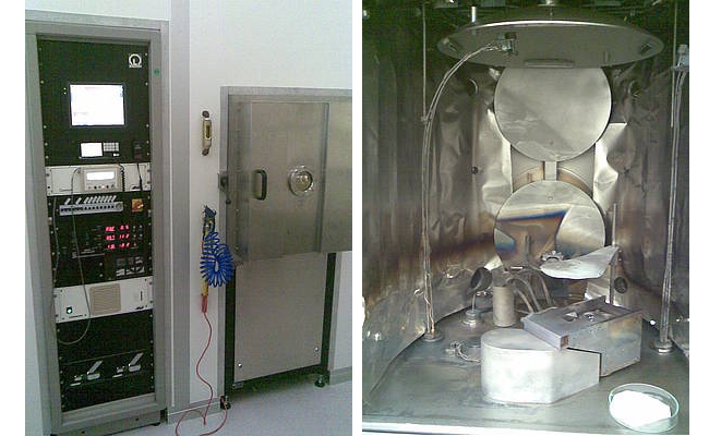
For the waveguide fabrication in lithium niobate (LN) two well-established techniques have been set up in our group: titanium-indiffusion (Ti:LN) and reverse proton exchange (RPE:LN) . In both cases, after sample preparation, a titanium layer of a specific thickness is deposited on the surface of the sample using e-beam evaporation (Fig. 1).
On top of the titanium layer we deposit a photoresist (PR) of ~1 μm thickness using a spin coater. After baking the resist we use a mask aligner for contact imprinting the desired structure information into the resist layer. The developed photoresist structure acts as protection mask for the subsequent etching process of the titanium layer. The etched Ti-structures are either slits (titanium acts as protective mask for RPE) or stripes (which define the guiding channels after indiffusion)
1.1 Titanium indiffused waveguides
To ensure the homogeneity of the future Ti:LN waveguides, the photolithographically defined Ti-stripes have to be homogeneous in width and height. With a Michelson interferometer attached to an optical microscope we determine the layer thickness with nanometer accuracy. The width of the Ti-stripes is measured using standard bright field microscopy in transmission mode together with an image processing software. After this quality check, the Ti-stripes are indiffued in a tube furnace at 1060°C in an oxygene atmosphere.
The photolithographically defined Ti-stripes act as diffusion reservoir and are completely exhausted leading to a channel of increased Ti-concentration inside the LN-substrate. The local Ti-concentration leads to an increase of ordinary and extraordinary refractive index. Therefore, Ti:LN waveguides allow guiding in both, TE- and TM polarization. The fabrication scheme of Ti:LN waveguides is shown in Fig. 2.
1.2. RPE waveguides
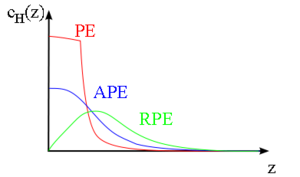
In principle our second waveguide fabrication technique in Lithiumniobate, reverse proton exchange consists of three single steps: proton exchange, annealing and the burying of the waveguide. All of these are independent diffusion processes, where the final state of hydrogen concentration after one step is the initial state for the next step. The most important technological steps are shown in Fig. 3.
1.2.1. Proton Exchange For the exchange of lithium against hydrogen ions the Ti- masked samples are immersed into a melt of a weak organic acid. Due to its low melting point and vapour pressure, most commonly benzoic acid is used as the proton source. Inside the mask windows an ion exchange is performed at about 170°C for several hours leading to channels of increased extraordinary refractive index (thus guiding only one polarization).
The as-exchanged regions of the substrate undergo structural phase transitions and the nonlinear relation between proton-concentration and index increase results in a step-like index profile and waveguides of high loss without any second-order optical nonlinearity.
1.2.2. Annealing Annealing reduces the proton concentration by diffusion deeper into the substrate. In this way structural phase transitions are reversed back to the so called low loss α-phase in which the optical nonlinearity is fully recovered and the relation between proton concentration and index increase is linear leading to a Gaussian-like profile. The annealing process is carried out at about 330°C for several hours.
The remaining strongly asymmetric concentration profile still results in asymmetric mode intensity distributions of non ideal overlap for nonlinear frequency conversion. To improve this overlap, to further reduce scattering losses and to optimize fiber-chip coupling a third step has to be carried out to achieve a buried almost symmetric waveguide.
1.2.3. Burying the waveguide In the regime of low proton concentration a symmetric proton concentration profile would lead to a symmetric profile of the extraordinary refractive index. When we drive the maximum concentration of protons deeper into the substrate this symmetrization becomes feasible.
Reversing the ion exchangeclose to the substrate means to out-diffuse protons and to in-diffuse lithium ions again. This can be achieved by immersing the sample into alithium-rich eutectic melt of LiNO3, KNO3 and NaNO3. The high gradient of proton concentration at the surface yields a stronger out-diffusion rather than a diffusion deeper into the substrate. As a result the maximum of the concentration profile moves into the substrate.
In Fig. 4 the three steps for the fabrication of RPE waveguides are shown schematically in terms of concentration profiles.


