
Electron Energy-Loss spectroscopy (EELS)
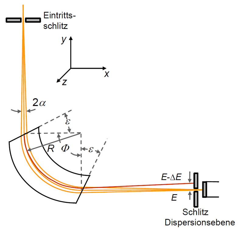
In EELS (electron energy-loss spectroscopy) the number of electrons is recorded as a function of the energy loss, which they have experienced in the specimen. Spectrum recording is performed with a prism spectrometer or an imaging energy filter. A magnetic field electron prisma is usually attached to the end of the TEM column. In the magnetic sector field the incident electron beam is deflected onto a circle, whose radius depends on the energy loss (Figure 1). A suitable inclination (ε ≠ 0) of the sector field edges against the electron beam produces focussing in radial and axial directions. Thus, a high resolution at large acceptance angle can be realised. There are two modes of spectrum recording: serial and parallel detection. In serial recording the spectrum is scanned across an aperture in front of a scintillator or semiconductor detector. Owing to the long recording time necessary for this mode the parallel i.e. simultaneous detection of the entire spectrum on a 1-dimensional photodiode array or a 2-dimensional CCD camera has won recognition.
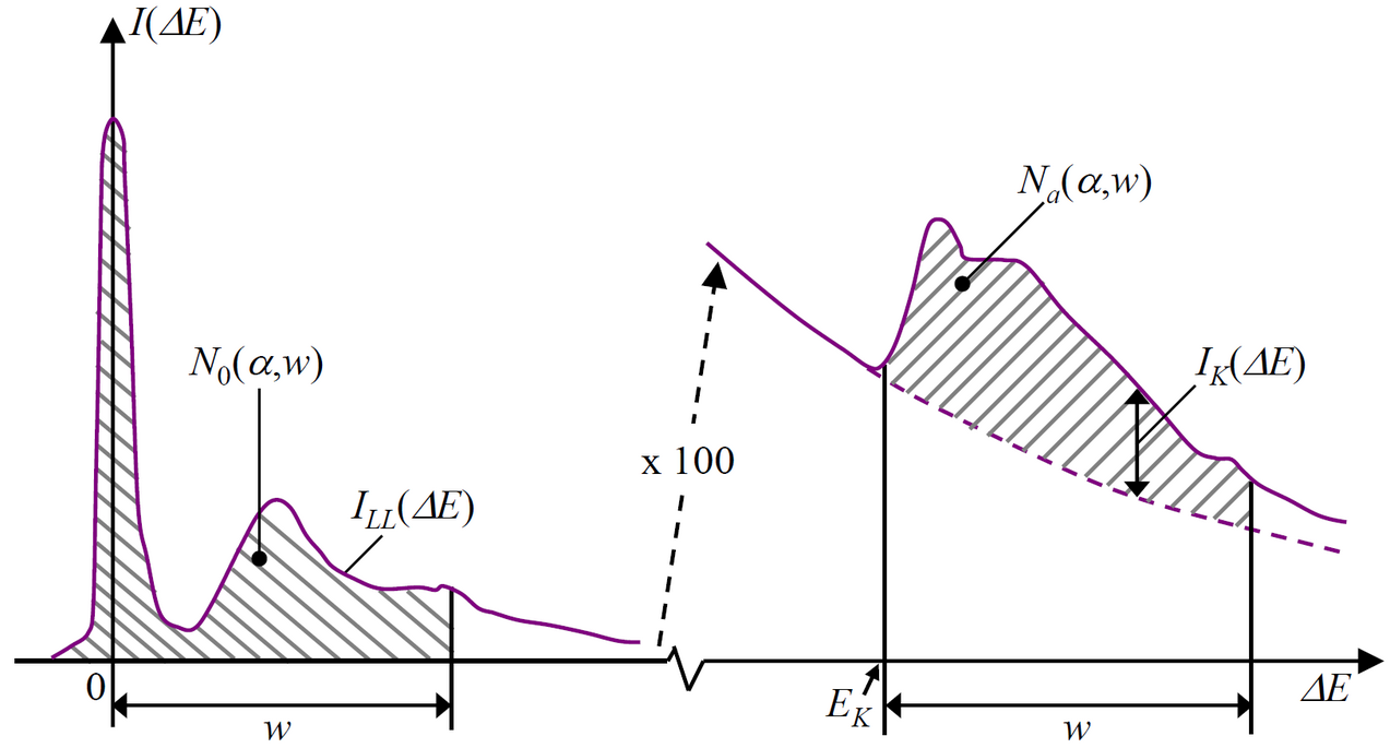
The loss spectra contain a wealth of information on inelastic scattering processes of the fast electrons travelling through the object. The so-called zero-loss peak comprises unscattered, purely elastically scattered as well as inelastically scattered electrons with unresolvably small energy losses (e.g. phonon scattering). In the region of low energy losses (< 50 eV) plasmon excitations, Cherenkov losses and intraband transitions are observable. At larger energy losses ionisation edges due to the interaction with core electrons occur in the spectrum. The ionisation of inner shells permits a quantitative analysis of the elemental composition (Figure 2): After subtraction of the background intensity and correction for multiple scattering effects the number of electrons of the energy loss intervals 0 ≤ ΔE ≤ w(N0) and EK ≤ ΔE ≤ EK+w(Na) are evaluated (EK: energy loss of the edge, w: width of the energy interval). Thus, the atomic areal density of element a is
na = (1/σa(α,w))*Na(α,w)/N0(α,w) ,
where σa denotes the partial scattering cross-section and α the acceptance angle. For large acceptance angles and small illumination apertures the edge intensity can be significantly influenced by the crystal orientation of the object.
Electron energy-loss near-edge fine structure (ELNES)
The electron energy-loss near edge fine structure (ELNES) occurs in the energy-loss region up to ~50 eV above the ionisation edge threshold. It results from the unoccupied density of states above the Fermi level. The shape of the ELNES depends on the bonding state and on the crystal structure. Due to unoccupied d states the ELNES of transition metal oxides displays a pair of intense lines, so-calles white lines, whose intensity ratio is correlated to the metal oxidation state. Moreover, the valence state of the atoms induces a chemical shift of the edge threshold.
Extended electron energy-loss fine structure (EXELFS)
The extended electron energy-loss fine structure (EXELFS) denotes weak intensity oscillations in the energy-loss region between ~50 eV up to ~200 eV above the edge threshold. Analogous to the fine structure appearing in X-ray absorption (EXAFS) EXELFS arises from the interference between the emanating wave of the excited electrons and the waves that are scattered at the neighbouring atoms. EXELFS enables the determination of the radial density distribution of the neighbouring atoms.
[1] L. Reimer, H. Kohl: Transmission Electron Microscopy - Physics of Image Formation, Springer 2008